fbpx

Real Pilots Fly Adcock Ranges

A look at the navigation systems that preceded today's technology.

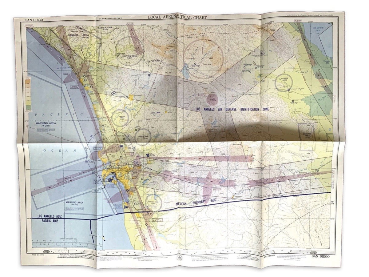
A friend bought me an old aeronautical chart he found in a map store. Dated August 16, 1953, it covers roughly the same area as the current Los Angeles VFR [visual flight rules] terminal area chart. In the lower margin are the words: “PRICE 25 CENTS.” You got more square miles for your money then than you do today, even taking inflation into account.

The scene depicted on the chart is at once familiar and strange. Many small airports have vanished; runway diagrams of some larger ones have changed. There are only three VORs [very high frequency omni-directional range]: Long Beach, Ontario, and Palmdale. The airways are 10 statute miles wide—the FAA did not go nautical until the mid-1960s—and they are defined by what look like localizers. They aren’t localizers, however; they’re the beams of four-course ranges.

Featured

At the dawn of aerial navigation, pilots found their way with landmarks and dead reckoning. After the postal service began shipping mail long distance by air in the 1920s, its pilots needed a better way of navigating at night, and the Department of Commerce responded by installing 1,500 beacon lights to guide pilots along commonly traveled routes. A few of these still exist, together with the 60-foot-long concrete arrows, embedded in the ground, that pointed to the next beacon. The lights established a rudimentary airway system but were useless for instrument flying. In marginal weather,as temptations, they were probably about as hazardous as they were helpful.

What made instrument flying commercially practical was the introduction of the low-frequency four-course range (LFR) late in the 1920s. Based on the radio direction-finding system invented and patented in 1919 by a Brit named Frank Adcock, it did not show the direction to a transmitter, as a non-directional beacon did, but instead defined geographically fixed lines for pilots to follow from one transmitter to another.

The ground installation for an LFR consisted of four 130-foot antennas at the corners of a square a few hundred feet on a side. Each diagonally-opposed pair of antennas broadcast a signal in two lobes which, viewed from above, formed a sort of figure-eight. Within those lobes, or “quadrants,” a Morse code letter was broadcast: either an A, dot-dash; or an N, dash-dot. If you imagine an LFR oriented so that one figure-eight lies north-south and one east-west, the north and south quadrants would be the N quadrants (by convention, the quadrant containing true north was an N), and the east and west would be A.

The timing of the dots and dashes was such that in the center of the area where two quadrants overlapped, you would hear a continuous tone. The lines of continuous tone formed the four courses or “beams” of the range. If all towers transmitted with equal strength, the beams would be at right angles. By altering the strength of individual antennas, the beams could be oriented to meet the requirements of airway intersections.

Pilots flying airways, stepping from one LFR to another, just had to keep the sound in their headsets continuous as they progressed from one station to another. (Actually, to avoid conflicts with opposite-direction traffic, pilots flew the right “feather edge” of the beam, where one letter just barely emerged from the continuous tone.) In practice, this meant finding the heading that kept the tone steady and then holding it, so that tracking the beam had much of the character of dead reckoning. The pilot would make small heading corrections from time to time to account for wind drift. You knew your ground speed from the time between previous stations, so you always had a pretty good idea of where you were.

As you passed over the transmitter array, there was a brief period of silence. In instrument weather, if the array was co-located with the destination airport, after finding the cone of silence you would fly outbound along the beam for 10 miles or so, make a procedure turn, and then follow the continuous tone back inbound. Otherwise, you might fly outbound from the cone of silence along a beam that led to the runway.

Not every flight followed an established airway, and pilots sometimes arrived in the vicinity of an LFR without knowing exactly where they were in relation to it. If you had not been absolutely scrupulous in your dead reckoning, this was a complex puzzle. You knew you were in an N quadrant or an A quadrant, but you might not know which one, or whether your heading was taking you toward or away from the station. Getting oriented consisted of finding a beam while monitoring the signal strength to determine whether you were flying toward or away from the station.

One of the convenient features of the four-course range was that the costly and complex part of its equipment was on the ground. The airplane needed only a simple audio receiver. Subsequent navigation systems would demand increasingly specialized onboard equipment. The first of these, appearing in the 1940s, was VAR or “visual aural range,” a hybrid consisting of two LFR beams and two high-frequency courses that amounted to a primitive VOR. On the map my friend gave me, LAX [Los Angeles International] has one of these, with a frequency of 109.1. It was located where the LAX VOR is today. The east-west beams, aligned with the runways, were marked B/Y, for Blue and Yellow. The northand south beams have the customary A and N. The additional Los Angeles Radio LFR, sited a few miles east of the airport, used 332 kHz, but I can’t find on the chart what frequency was used for the low-frequency beams of the VAR. Perhaps some old-timer can tell me.

VAR had a panel display with a swinging needle and a background split down the middle between blue and yellow. This was the “visual” component, in contrast to the aural character of the low-frequency range. Its use would be clear to any pilot familiar with VOR navigation but must have been quite a novelty when it first appeared in the 1940s. VAR had a short life as navigational methods go; it was replaced by VOR, which, instead of being limited to two courses, had 360 of them. If memory serves, VOR originally stood for “visual omni directional range,” the word “visual” inherited from its predecessor. Later, when visual displays became common, people began saying instead that the V stood for “very high frequency,” and so they say today.

But cast your imagination back 80 years. You’re in a cargo-laden Douglas DC-3, iced up ever since you dropped into the cloud tops, you’re losing altitude, and you’re low on fuel. Thunderstorms have winked at you all evening; it’s pitch dark now, there are mountains all around, and at last, you’re picking up a faint dot-dash from Prescott, Arizona, through the static. You increase power a little, roll into a turn, and start your hunt for a beam.

All things considered, I think I prefer GPS.

This article was originally published in the March 2023 Issue 935 of  FLYING.

Login

New to Flying?

Register

Already have an account?