fbpx

The Link Trainer: An Uncommanded Roll Gets Our Author’s Attention

A popular 1940s-era flight training device is the mechanical predecessor to the modern sim.

I have logged in excess of 3,000 hours in a Redbird FMX Advanced Aviation Training Device. These are the devices that are mounted on cradles that provide the unit with pitch, yaw, and roll. One of the biggest surprises for the trainees who have been “flying” using the Microsoft Flight Simulator program and then try to fly the FMX is how quickly their instrument scan and aircraft control goes askance when the dimension of movement is added to the equation.

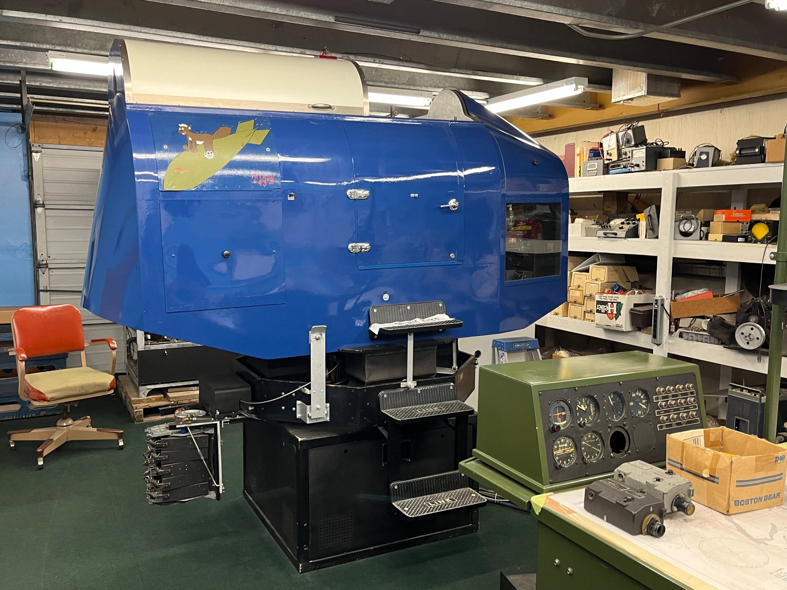
I was thinking about this yesterday when I climbed into a Link Trainer at the Museum of Flight Restoration Center at Snohomish County Airport/Paine Field (KPAE). For the unfamiliar, the Link Trainer was designed in the 1920s by Edwin Link of Binghamton, New York. During World War II, Link trainers were used extensively to train pilots to fly by instruments.

You’ve probably seen one of these in a museum or in historic newsreel footage that shows a cartoon-like aircraft (reminiscent of a carnival ride) spinning on the floor of a hangar while serious-looking air cadets try to learn the ins and outs of IFR flying. The devices are about the size of a small car, and are mounted on a mechanical cradle. Cables run from the sim cab to a desk where an instructor has a console to put the pilot through his (or her) paces. It is very, very rare to find one that still functions, as most are relegated to static display at aviation museums.

My flight in the MOF’s Link Trainer was the maiden voyage after years of restoration.

First Impressions

I am one of those pilots that learns well in a simulation environment. The names Precor, Frasca, OneG, AST300, Redbird, and the TouchTrainer FM-210 appear in my logbooks in both the “Instruction Received” and “Instruction Given” columns.

My tour guide for the day was Austin Ballard, who is in charge of the MOF Restoration Center. He was quick to note the Link C-3 restoration was a multi-year, multi-person job. I would be remiss if I did not recognize volunteers Joe Polocz, Don Milsted, Charlie Price, Ed Essex, and Bobby Takatsuka for their fine efforts during my Link training session. But would this ancient machine, designed in the time of Lindbergh with vacuum tubes, pulleys and bellows, and cables still work?

We would find out.

Ballard cautioned me that one needs to be agile—and careful while climbing inside the Link Trainer. The cockpit is about 2 feet above the floor. There are steep steps, and you have to grab the side of the cockpit and sort of swing yourself inside. One must take care that the door doesn’t smash their fingers. One must slide the overhead canopy all the way forward in order to have room to maneuver. There is not a lot of room and the seat is not forgiving—it feels a bit like sitting in a wooden pew at church.

The Link is powered by electricity, which actuates mechanical motors, which actuate bellows, and there are pulleys and belts to give you the sensation of pitch, yaw, and roll. The instructor’s station is located off to the side on a desk. The Link does not roll inverted, so you do not need a seatbelt.

At the Controls

The start switch was flipped. There was a whirring noise and after confirming that the Link was not in the locked position (check the lever in the cockpit), it began to drift slowly in a circle.

The machine operates with vacuum tubes, and those require time to warm up. While that was happening, I acquainted myself with the instrument panel. I have some time in 1940s-era machines so I was familiar with most of the round dials I was looking at.

The instrument panel of the Link Trainer. [Photo: Meg Godlewski]

The attitude indicator, black and white with the stylized airplane over the horizontal line, looks downright primitive if you have been raised on the AIs with blue on top, brown on the bottom and the horizontal lines for 5 degrees, 10 degrees, and so forth. The vertical lines for 10 degrees, 20 degrees, and 30 degrees were on the ancient instrument. I recalled the training acquired from my mentor, Dean Boyd, who said climbs were done by pitching the aircraft above the horizon line gauging it by wing widths while simultaneously keeping the ball in the center and watching airspeed and heading.

The slip-skid indicator and the ball haven’t changed much in 75 years. [Photo: Meg Godlewski]
The rudder and aileron trim are on the left side of the cockpit under the throttle quadrant. [Photo: Meg Godlewski]

The slip-skid indicator was familiar, although the ones in the aircraft I trained in had sort of an upside-down doghouse shape on top that, when the needle was placed there, indicated a standard-rate turn.

The airspeed indicator to the left of the compass was familiar as were the altimeter and vertical speed indicator.

The yoke of the Link is the steering wheel type, reminiscent of those on the 1930s to 1940s twins I have flown. The rudder pedals are around the size of an iPad. Anytime I see large rudder pedals paired with a large yoke, I think about over-controlling—big rudder and wheel often means an airplane takes two hands and is trim dependent. I quickly located the aircraft trim actuators, which are knobs on the left side of the cockpit. That’s also where I found the throttle, propeller, and mixture levers.

The rudder pedals are large by modern standards. [Photo: Meg Godlewski]

The flaps and landing gear levers are located behind the pilot on the left. I thought that was a weird place for them, and wondered if it led to any negative transference in the real aircraft.

Scan Challenges

I tell my learners to think of the instruments on the panel like a box of kittens—you can’t fixate on one, because the rest will get out and there will be drama. This is where the pilot develops their scan—it’s a lot easier to scan when the instruments are closer together in neat rows with the attitude indicator, arguably the most important instrument flying, front and center in the pilot’s field of view. That is not the case in the Link Trainer.

Before “engine start” the attitude indicator is not aligned. [Photo: Meg Godlewski]

The attitude indicator is in the top right—to the left is the magnetic compass, and underneath it, the slip-skid indicator, with the altimeter to the left. I figured my scan was going to be sort of rhombus shaped.

Once I was settled into the machine, the door was closed and the overhead hatch slid back, putting me into darkness with the exception of a few panel lights and slivers of light coming from right where the instructor’s access portal is located.

On the backside of the device is the instructor’s window. [Photo: Meg Godlewski]

Ballard explained that instructors could open the access portal to view the trainee. There are also toggle switches next to the port access on the outside of the Link which the CFI can use to fail instruments.

Mechanical Difficulties

On the subject of failure, on this day, we experienced one of the mechanical variety. As the Link Trainer became operational, it rolled to the right. It was an uncommanded roll, surprising both Ballard and myself.

“Yoke left!” he called from outside the Link.

I grabbed the yoke and put it all the way left—and nothing happened. I added left rudder. Nothing happened. After a few moments of exterior inspection, Ballard determined that the leather belt that actuated the yaw of the Link Trainer had failed.

“Where do you get replacement parts?” I asked, knowing that this device was at least 75 years old.

“You make them,” he laughed.

Apparently, my training in the Link will need to be continued another day. 

Login

New to Flying?

Register

Already have an account?