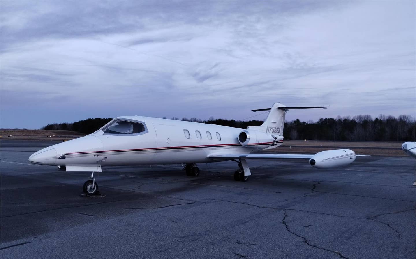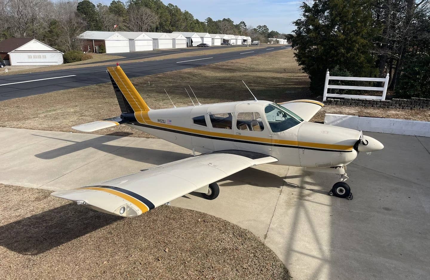
Possibly the most widely used airfoil of all time, the NACA 23012 combined high lift, low drag, mild pitching moments, and even a bit of laminar flow on its lower surface. It was designed in 1935 by NACA Langley researcher Eastman Jacobs.
Let's be frank. We don't really need airfoils. Model planes with flat sheets of balsa wood for wings fly nicely; so do airplanes made of folded paper, and bumblebees and butterflies. A flat sheet makes a perfectly serviceable wing.
That flat surfaces in the wind could produce the sideways force that we now call lift was a very ancient observation. Two early applications of it, the windmill and the fore-aft rigged sail, date back at least 800 years. It was also perfectly evident to any thinking person that what kept birds and bats aloft was the large flat surfaces attached to their arms. Neither the feathers of birds nor the fabric of sails and windmill blades had any thickness to speak of, and so the earliest lifting surfaces were just that: surfaces.
Thin surfaces restrained by a supporting structure naturally bellied out under air pressure, assuming what we now call a "cambered" -- that is, arched -- shape. The fact that camber was actually beneficial seems first to have been appreciated -- at least in writing -- by an English civil engineer of the 18th century, John Smeaton, who noted that curving the surfaces of their blades improved the performance of windmills.
For the next century and a half, nothing noteworthy occurred -- other than the invention of the modern airplane, in 1804, by another Englishman, George Cayley.
When we arrive at the beginning of the 20th century, we find the Wrights conducting systematic wind tunnel experiments to determine not only the best amount of camber to use, but also the best fore-and-aft distribution of curvature. The Brazilian Santos-Dumont, whose 1906 Paris flights in his huge 14-bis ("Number 14 encore") are considered by some to have been the first true powered flights because his airplane rolled and rose under its own power (the Wrights employed a catapult and rail to get airborne in 1903), used very little camber, perhaps because he knew that it made an airplane want to dive. On the other hand, the wings of the Bleriot 11 that made the first aerial crossing of the English Channel had a great deal more camber than they needed.
A number of early airplanes had sail-like wings, consisting of a single skin sewn to spars and ribs. Such a wing lent itself to wing-warping, which was the earliest form of roll control. Once ailerons appeared, wings had to be made rigid. By the time the First World War began, well-streamlined biplanes of rather good performance were the rule; their wings had smooth top and bottom surfaces with the structure hidden inside. Their cross-sections scarcely deserved the name of airfoils, however. They were actually just eel-like shapes, rounded at the front and tapered more or less to a point at the back, and thickened just enough to envelop the necessary internal structure.
Despite the random and ad hoc quality of these early airfoil designs, efforts were being made to sort out the wheat from the chaff in wind tunnels. At first, unfortunately, investigators did not recognize the importance of scale. They tested very small models at very low speeds, and, because speed and size actually play important roles in the behavior of flowing air, their results supported the mistaken guess that thin airfoils were superior.
By 1917 the gray eminence of German aerodynamic research, Ludwig Prandtl, had a wind tunnel at Göttingen large enough to allow testing of full-scale airfoil sections at realistic speeds. He also had a mathematical method of creating airfoil-like curves. He quickly discovered the superiority of thick sections, whose larger leading-edge radii allowed them to reach higher angles of attack, and thus to produce more lift before stalling, than thin ones could. The long-held belief that thicker sections must have greater drag also proved to be false. Anthony Fokker immediately adopted thick airfoils for the triplane of Red Baron fame. The British and French builders persisted with their thin airfoils through the end of the war, but then abandoned them.
During the 1930s the U.S. National Advisory Committee for Aeronautics, or NACA, developed and tested "families" of airfoils. Some of the most successful of these were the NACA four-digit and five-digit series, which consisted of a "basic thickness form" -- a symmetrical "teardrop" shape-superimposed on a "camber line" from which the profile derived most of its aerodynamic characteristics, such as the amount of lift it produced at an angle of attack of zero, and the strength of the "pitching moment" or diving tendency that camber tended to produce. Many of those sections are still in use today, and NACA's 23000 series, created in 1935, is probably the most widely used airfoil in history.
Despite all the highly technical theoretical work done by NACA, there continued to be a parallel tradition of what might be called barefoot airfoil design. It grew out of the recognition that the airfoils on real wings, many of which were still skinned with fabric at the time, did not bear much resemblance to idealized wind tunnel models. In practice, anything that looked like an airfoil worked like an airfoil. The finest flower of the barefoot school was the Clark Y, a 1922 invention of a Colonel Virginius Clark, who arrived at it by the highly unscientific expedient of deforming one of the wartime Göttingen airfoils to make the aft 70 percent of its bottom flat. The flat bottom turned out to be a very attractive feature. It facilitated construction (especially for modelers, who flocked to the Clark Y because it allowed them to make a wing straight by simply pinning it down to a flat surface while the glue dried) and measurement of angle of attack, and it simplified the carving of propeller blades. In spite of its possessing no special aerodynamic merit, the Clark Y has been used in a great variety of airplanes. (A remarkable listing of hundreds of aircraft types and the airfoils they use can be found at ae.uiuc.edu/m-selig/ads/aircraft.html.)
By 1940, airfoil development had passed three milestones -- or at least what I think of as milestones. The first was the general recognition, not due to any single investigator, that camber aided the production of lift, and that if an airfoil had more than negligible thickness it needed to be rounded in the front and somewhat sharp in the back. The next was the discovery, due to Prandtl, that thickness -- meaning thickness greater than, say, a tenth of the chord length -- was beneficial. The third milestone was the systematization of profiles -- largely the work of a NACA Langley researcher named Eastman Jacobs -- into "families" with well-documented characteristics, which allowed designers to select suitable sections from a catalog. (By the way, the words "airfoil," "profile" and "section" are synonymous as I am using them.)
The fourth milestone was a revolution in the relationship between mathematics and airfoil design. From the early days, various kind of mathematical functions had been used to generate airfoil shapes. But these procedures were not based on the physics of fluid flow; they were just equations that happened to produce smoothly curved lines that looked like airfoils. In 1931, another NACA aerodynamicist, Theodore Theodorsen, invented a mathematical method of calculating the pressure distribution on any airfoil. The pressure distribution is very important; it is the key to the airfoil's drag, lift and stalling behavior.
Theodorsen was a confident fellow. When his calculated results did not precisely coincide with wind tunnel measurements, he airily dismissed the empirical results as unreliable. Relations between Theodorsen and the experimentalist Eastman Jacobs were prickly, and when Jacobs, playing against type, proposed reversing Theodorsen's method in order to obtain an airfoil shape that would generate a desired pressure distribution, Theodorsen dismissed the idea as mathematically nonsensical. Jacobs persisted, however, and he succeeded in creating the procedure used to design profiles in digital computers today.
The first fruit of Jacobs' work was the natural laminar flow airfoil. (Natural, in this context, means that no powered method, such as boundary-layer suction, is used to maintain laminar flow.) His work was based on the knowledge that the behavior of the boundary layer -- the thin layer of air, close to the airfoil surface, that the airplane drags along with it -- is influenced by the pressure distribution. A laminar boundary layer, in which all air particles follow paths parallel to the airfoil surface, could be sustained along the front of an airfoil, as its upper and lower surfaces grew farther apart. But when the surfaces began to converge, tiny turbulent eddies and vortices would appear in the boundary layer. The drag of a laminar boundary layer is much less than that of a turbulent one. All airfoils have some laminar flow, but the new family of laminar profiles developed by the NACA extended the laminar boundary layer to as much as 60 percent of the airfoil's length, reducing drag by as much as two-thirds.
As John Anderson notes in his History of Aerodynamics, the laminar airfoils, first used on the P-51 Mustang, were successful in reducing drag in the wind tunnel but less successful in the field because the irregularities of practical metal construction, along with general wear-and-tear and unavoidable bug splatter, would disrupt the tempermental laminar boundary layer. Yet they proved to be successful in an unexpected way; laminar-flow sections, with their maximum thickness far aft, turned out to be well-suited for high-speed airplanes, because they were less prone to early formation of transonic shock waves. Anderson might have added that they had some success, even in the field and on low-speed airplanes, when composite wings came into use. A high-performance sailplane with a non-laminar airfoil is unthinkable today.
The fifth milestone in airfoil evolution comes with the development of foils especially designed for flight below, but close to, the speed of sound. These so-called supercritical airfoils have thick noses, flattish tops and aft camber, all characteristics designed to delay the onset of shock waves due to local supersonic flow.
You might suppose that supersonic airfoils would represent yet another great advance, but in fact they are not airfoils in the normal sense at all. The laws of supersonic flight are entirely different from those of subsonic flight, and purely supersonic wing sections dispense with sophisticated camber and thickness distribution; a flattened diamond shape, or even, as on the stabilizing surfaces of the X-15, a triangle with a bluff aft end, is sufficient. A knife blade is as good a supersonic wing as anything else. The wings of supersonic airplanes do, in fact, still have airfoils -- generally very thin ones -- but that is only because they take off and land at subsonic speed.
Today, it is routine to custom-design the airfoils for each new airplane on a computer. In a way, as Anderson remarks, airfoil design has come full circle. In the early years, each new airplane might get a new airfoil. The same is true today-but today we no longer design new airfoils in ignorance of how they work.

Subscribe to Our Newsletter
Get the latest FLYING stories delivered directly to your inbox


