Runway visual range, or RVR, precisely measures the distance that a pilot flying an ILS approach might expect to see when looking down the runway in those critical seconds just before touchdown. Because landing and some takeoff minimums are based on visibility, an operating RVR system is a vital operational element to support the high arrival and departure rates demanded at busy airports.
How It Works: Runway Visual Range
Key Takeaways:
- Runway Visual Range (RVR) precisely measures the distance a pilot can see down the runway, crucial for supporting high arrival and departure rates at busy airports where landing and takeoff minimums are based on visibility.
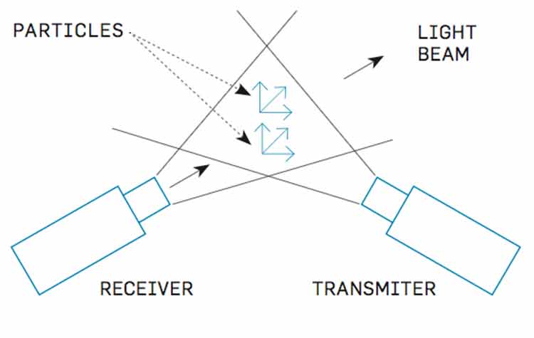
- An RVR system integrates several components, including forward scatterometer visibility sensors (VS), ambient light sensors (ALS), a runway light intensity monitor (RLIM), and a data processing unit.
- These strategically placed sensors work in conjunction to measure atmospheric particle density and background lighting, enabling the accurate calculation and display of RVR readings to air traffic controllers.
Key takeaways sponsored by Aviator Pro | Start Your Training ->
See a mistake? Contact us.