
An angle of attack indicator offers a visual indication of the amount of lift the wing is generating at a given airspeed or angle of bank. The AOA delivers critical information visually or through an aural tone to indicate the actual safety margin above an aerodynamic stall.
AOAs are created around one of two systems, either a lift reserve indicator or a normalized AOA. An LRI is normally accurate in a single configuration, usually near the approach angle of attack. The advantage of a normalized AOA is that the angle of attack measurement is accurate in all aircraft configurations. The normalized AOA is in use on Dassault’s Falcon 7X and 8X, the Airbus A380 and nearly every jet produced by Embraer.
Both AOA configurations consist of a heated wing probe that looks similar to a standard pitot tube. Both AoA versions also require an air-data computer and a visual cockpit indicator.
The AOA tube is constructed with two tiny machined holes to create differential pressure sources. One hole is bore-sighted at the front of the AOA tube along the longitudinal axis, while the second, located at the bottom of the AOA probe, is pointed downward at a 45-degree angle to act as a reference source.
Garmin’s normalized AOA includes an additional static-air-pressure source to allow the air-data computer to calculate airspeed and air density, important in calculating precise AOA. The addition of the static-pressure reference input makes the AOA indication accurate regardless of the airplane’s weight, speed or configuration. This comes in handy particularly in steep turns when a pilot normally adds back pressure to maintain altitude, something that also increases the angle of attack and the airplane’s stall speed. In order to ensure accurate data, each AOA must be calibrated for the specific aircraft in which it is installed.
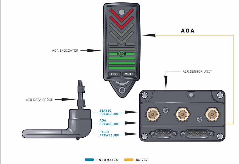
On a normalized AOA, air pressure passes from the probe through flexible tubes in the wing until it reaches three pressure sensors co-located with the air-data computer’s microprocessor. It is here the translation occurs to create the electronic signals sent to the cockpit indicator.
The AOA indicator, in our example measuring approximately 3.2 inches high by 1.4 inches wide, is often mounted on the top of the glare shield, where it can be easily seen through the pilot’s peripheral vision during most flight conditions.
In cruise, the AOA is dark. As the angle of attack increases, the AOA indicator (shown on the opposite page)first illuminates the green bar near the display’s bottom. As the angle of attack increases, additional green bars light up until the green dot — called the donut — illuminates, indicating the proper final approach path angle. If the angle of attack continues to increase, the green bars will turn yellow as a caution and, finally, red as the wing approaches a stall.
One hurdle to widespread AOA implementation is the need for CFIs to understand and teach a useful tool most have never actually used themselves.