fbpx

The Adventures of a Panel Redesign

Limitations are inherent in modifying old panels.

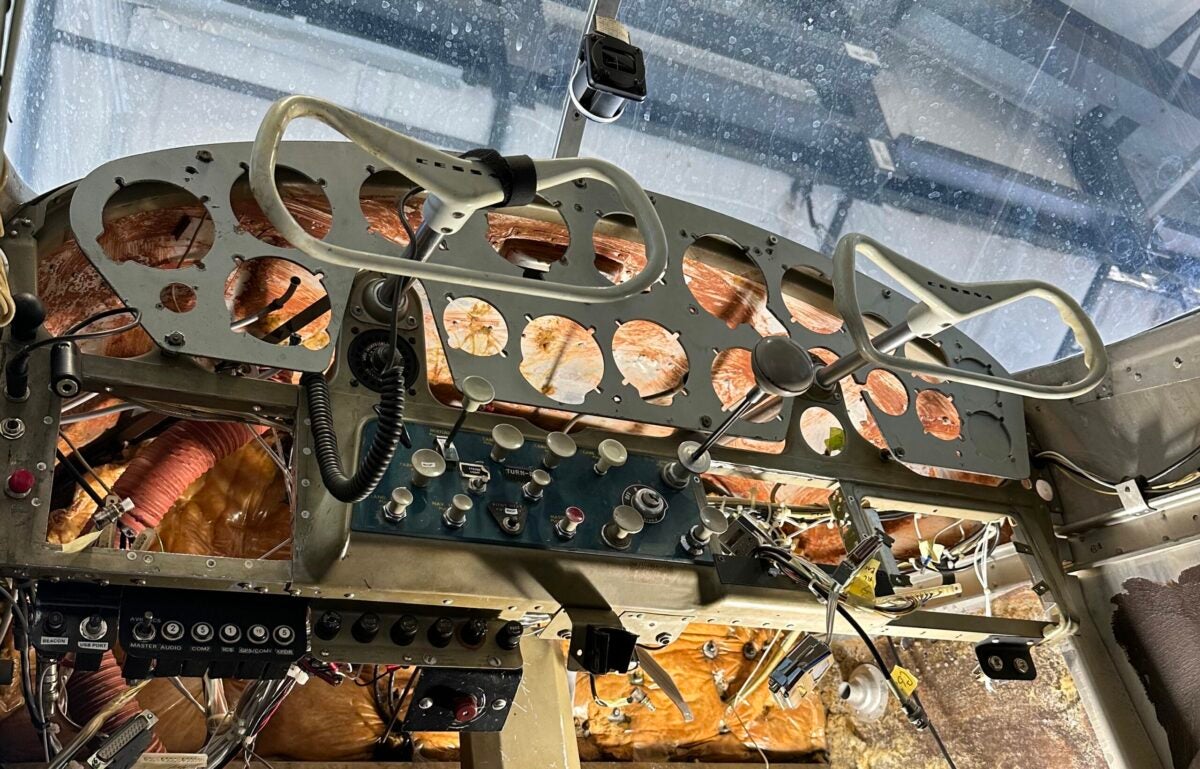
When I decided to spend a not-insignificant sum of money on a complete redesign and rebuild of my instrument panel, I was excited. Over the years, previous owners of my airplane made some bizarre decisions with regard to panel layout, arranging things oddly and inexplicably adding a second altimeter. A new panel would be an opportunity to start from scratch, positioning each instrument, radio, switch, and circuit breaker precisely where I wanted them. 

Or so I thought.

Going into such an endeavor with zero knowledge of panel design, I assumed the process would be as simple as arranging magnets on the front of a refrigerator. I fired up Photoshop, found photos of all the avionics I was planning to install, and got to work positioning them to my heart’s content. 

First on my list of priorities was repositioning the radios, transponder, and GPS. In my airplane, these are presently all relegated to the very bottom of the panel. Half are down by the pilot’s left knee, and the other half are over by the passenger’s left knee. They are so far out of the pilot’s line of sight one must occasionally duck to see the frequency windows. It’s annoying, and it’s a distraction.

As I designed my ideal layout, I immediately set out to relocate the radios. All would be grouped together in perfect alignment and positioned in the exact center of the panel, easily accessible by either front-seat occupant. Additionally, they’d be up high, nicely in the field of view, and easily referenced during flight.

Similarly, I opted to position the engine-monitoring unit directly above the throttle and mixture. It seemed logical that they be placed adjacent to one another. There seemed to be plenty of space for this, and I gave it no second thought as I pasted its likeness onto my Photoshopped panel.

Finally, I positioned the attitude indicator and horizontal situation indicator (HSI) in the most prime panel real estate available—directly in my field of view, above the yoke. Though I didn’t need to retain the analog airspeed and turn/slip indicators, I did so. I liked the idea of airspeed and coordination being represented by relatively large shapes that physically move and are thus a bit more noticeable in my peripheral vision.

Several hours later, I had created an extraordinarily poor-quality representation of my dream panel. Though severely pixelated, out of alignment, and not scaled properly, it seemed the perfect arrangement. Like a kindergartener presenting their artistic creation to their parents, I proudly presented my dismally-Photoshopped creation to my friend Jessica Voruda at NewView Technologies, an avionics and maintenance facility in nearby Oshkosh, Wisconsin. 

Photoshop, while primitive, serves as a tool to help form initial panel layout plans. [Credit: Jim Stevenson]

Ever the professional, Jessica took pity on my feeble understanding of avionics installs. Marking my mock-up with red Xs like a teacher correcting a student’s test, she patiently explained the limitations inherent in modifying old panels. And there are quite a few to contend with.

As it turned out, two critical concepts had escaped me. First, many radios and avionics are quite deep, extending well into the panel toward the firewall. And second, some aircraft types require ample internal volume within a panel to provide the inner workings sufficient freedom of movement. 

Jessica explained that most of the new avionics I was planning to install had to remain clear of the entire central portion of my instrument panel. She further explained that, inside my panel, I’ve got a large central column shaped like a T that connects the two smaller control yokes. Because of the slope of the upper cowl, there’s a minimal amount of space above this column. 

Additionally, when the control yokes are pulled back, this T-column moves in unison. It is, therefore, critical that nothing impedes its range of motion. New radios and avionics, for example.

Interference issues from two sides are visible here – the sloping upper skin requires certain instruments to be positioned lower on the panel, but the black T-column requires sufficient clearance to pivot backward with the control yokes. [Credit: Jessica Voruda]

As with most matters of aviation, it is entirely possible to throw money at the problem until it goes away. In my case, I could source and install a newer U-column with available conversions that would provide sufficient internal clearance to clear a central radio stack. However, this solution was expensive and time-consuming, and my budget was already stretched thin.

So it was back to the drawing board. Armed with a quick education and better images to drag around in Photoshop, I worked on creating a layout that was compatible with my newly-learned technical constraints. After several days and many revisions, I presented a modified plan to Jessica. After a few minor tweaks of her own, we settled on a final plan and prepared for the fun second phase—how to incorporate minor changes and introduce design elements to balance modern capability with original, vintage design.

This initial phase was an interesting and educational one, however. It underscored the importance of finding and selecting an avionics shop with people who possess the patience and talent to educate and work with you along the way. Working with an impersonal shop that cares more about its bottom line and schedule, you feel like a number, like you’re just along for the ride. 

But with shops and technicians that explain every step of the process and patiently walk you through it, the entire project becomes that much more enjoyable and educational. I’m thankful to have found such a shop and such a technician. Spending tens of thousands of dollars is stressful enough, after all, and thus far, my experience has been a lot more fun than I expected it to be.

Login

New to Flying?

Register

Already have an account?